For this workshop we were given the task of modelling the character from the reference sheet that we selecting during our last lesson, however with our lack of experience in character creation this will be a rather tedious and time consuming task as we will also need to learn new skills during this time.
This is the character that I will be creating.
Pt.1. Torso and Arms.
The first step to creating this character is to create the torso and the arms, to begin the creation process I created a cylinder with 4 subdivisions across and 8 going around, this gives us enough geometry to give the model a high quality look; this is very helpful when developing a game as the more polys you have, the harder it becomes for the engine to render the character; resulting in lower frames and poor performance. Next I created a cylinder with 6 subdivisions around, with 6 across; following the same process of manipulating the vertices and edges, I created an arm. Now it was time to connect the arm to the body, this is quite a difficult task to do, but to start I first extruded 4 faces outwards from the shoulder; by doing this it gives a better shape of a shoulder that matches the angle of the arm, making attaching it afterwards far easier. Once I am ready to attach them, I combine both the torso and the arm meshes; allowing me to grab the vertices on both meshes, and snap them together by holding V when moving them. Once all of the vertices are together and where I wanted, I highlight them all and use the Merge tool ().
Doing this method, however, can often cause issues with misalignment of the topology of both the arm and torso when connected, but this is not a difficult to solve; as all it requires for you to do is use the multi-cut tool or insert edge loop tool, these will add loops and vertices to attach them. Now the topology should flow, from the arms up to the neck, and then from the underarm to underneath the arm.

Pt.2. Hands.
The creation of the hands used the same technique of manipulating the edges and vertices. I started off with a cube, then matched it roughly to the size of the palm. To add fingers; first start with adding edge loops, this creates squares, I then extruded these squares multiple times until I had each joint in the fingers. The thumb is a little more difficult to create, since it isn’t as simple as making straight squares like the fingers, firstly I created the part that connects the thumb to the index finger and rotated it to fit the angle of the hand. Once this was done, I was able to extrude the rest of the thumb out. The clothing featured on his hand like the glove was created by using basic extrusion of the faces to make the hand thicker, given it the look of the glove he is wearing.


Pt.3. Legs.
Creating the legs is very similar to the creation of the arms, as we start off with creating a cylinder with 8 subdivisions around and 6 across. To make it look like the reference image I once again moved the vertices around to line it up with the images in the background. Finally, to make the leg and torso on piece we used a similar process to the one used to connect the shoulders and arms, I started off by extruding the top faces upwards, and using the snap to vertice tool, I connected the legs to the crotch by aligning each vertice to each other; finally I selected the merge tool to make sure that there were no overlapping edges or vertices. This was by far the easiest part of the workshop so far as the shape of both the model and the reference shape was rather simple and easy to manipulate accurately.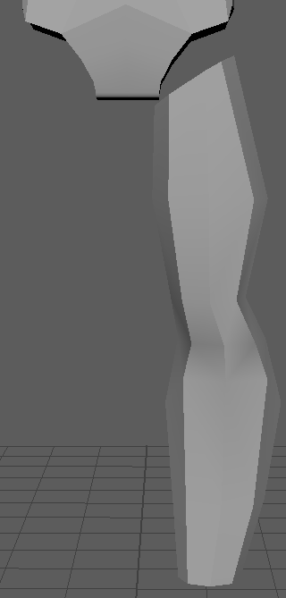
Pt.4. Feet.
Creating the feet has been the hardest part of this workshop as of yet, during this stage I restarted the foot numerous times due to how difficult it was to accurately translate stylized 2d shoes to a 3d model. To start off the process I brought in a cube, then added a few subdivisions. Secondly I moved the vertices to match the reference image as best as I could. Next, I had to try to make the feet look like a shoe; this was the part where I seriously struggled, as unlike the rest of the modeling previous to this the reference image does not give me enough detail on what the shoe really looks like. This resulted in me having to guess what it looked like in a 3d setting, meaning that I had to basically create it from scratch, and as I said during my research, modeling from no reference is rather difficult as there is nothing to base the measurements and shape of the model on.
Once I had created a good enough foot shape, I connected it to the ankle using the same method for the attaching the leg and torso, however the various issues i faced during modeling of the foot had caused serious misaligned topology on the foot alone, this then became a challenge when it came to lining up the foots topology with the legs topology.
Pt.5. Head.
This was the most difficult part of the entire workshop, as creating human heads is a difficult task thanks to the anatomy; especially considering how each part of the face can often be at different depths, meaning there is no symmetry, thus removing the ability to just create one half and mirroring it across. However, as we chose a cartoon design Deadpool’s face is far simpler than a human face, so this makes it far easier as we only need to design the one half.
I started this off with a cylinder, and giving it 12 subdivisions around. Then taking the inner vertices I adjusted them to fit the shape of the eyeball. Finally, I removed all faces except the front ones, leaving me with a 2D object.
Once that was done, I took the outer edges and extruded them, I then adjusted the vertices to add depth; this was to create the upper cheek bone and the eye brow. Matching the side perspective was rather difficult as the side on reference wasn’t quite correct in terms of height when line up next the front one view, this meant that I had to do some guess work to get it to look like the original character as much as possible.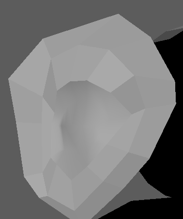
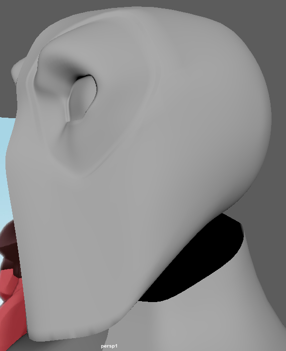
Next, I started working towards creating the rest of the face, this process started off by extruding the center piece of the face; as the mask, thankfully, doesn’t feature any detailed pieces like: ears, a nose or a mouth, it wasn’t necessary for me to spend hours trying to create these detailed pieces, as these are often the hardest part to create when modeling a face. For the top faces, I just extruded them out to the left and snapped them onto the grid by holding X while manipulating the vertices. This method didn’t work for the long pieces where the mouth should be, so to do this I had to extrude straight down and merge the vertices later on to turn it all into one piece.

To help me visualize the topology needed later on when I attach the face to the rest of the head, I created a sphere and reduced the edge loops to 12. To allow me to connect face onto it later, I removed some faces; leaving me with a Pac-Man like shape. I then started to adjust the position of the face to help me create both the jaw and the chin. This was very simple, as you only really need it to match the side view reference.
Now that the back of the head and the jaw had been added created it was time to create the head as a whole from a smooth point of view, however before I can do this I must connect the face and skull together. This is done with a similar approach as the connecting the other limbs to the torso, however, this was a little more difficult due to it being a sphere, and for reasons i do not understand the topology was far from similar to the flat plane that was the face. Unfortunately, inserting edge loops doesn’t always work, however, the multi cut tool worked wonders for this,but I was left with some triangles in my model. Now that the head is one piece it was time to model in smoothed mode, by pressing 3 when the model is selected, Maya smooths out the faces to create a more natural rounded effect; we are going to use it to create a more natural face, rather than a very blocky face. However, Maya will smooth out nearly everything, and as i desired parts of the face to smooth, I do not want a completely round character. This is where the crease tool comes into play, with it you can dictate what is smoothed and what isn’t. 
Pt.6. UV Mapping.
Now that we have completed the modelling stage of the workshop, it is time to UV map it ready for texturing.
I started out by planar mapping the face on the z axis, since that is the direction that the face was actually facing. This gave me a good quality UV shell.
For both the legs, arms and the torso, I followed the same steps as the head; as they face in the same direction.
One thing that proved to be invaluable to this whole process was the expand and shrink selection hotkeys; by using SHIFT + </> you are able to both expand or reduce the current selection.
When I planar mapped the foot I decided on using the Y axis as I believe that I would be most beneficial to work on the foot from above as it gives me the most surface area to work with out of all the angles.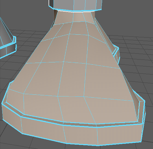
When working with UV maps, the maps must be unfolded, making easier to use for both the user and the computer. Unfolding is the process of cutting a seam upon which the UV shell is unfolded from. Before i was able to unfold the UVs I first needed to add seams to the model where I want it to unfold from. To cut the seams into the model, I used the cut tool located in the UV section when selecting the edges that I wished to become the seam for that limb. I also cut a seam into the underneath of the arms, the back of the head and torso, the inside of the legs and going through the sides of the hands and feet. Cutting these seams allows me to unfold the UVs later on in the workshop.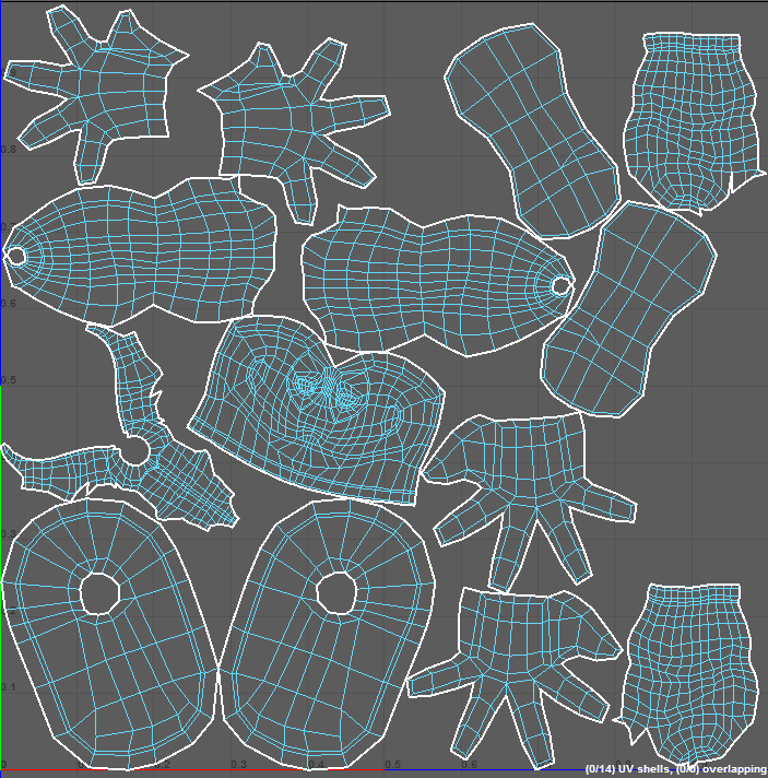
Since the previous UVs we mapped were only for the one side, I had to mirror them. This gives me two sides of the mode, which can be cut and sewn together at a later time.

By taking edges from 2 different UV shells that belong together and using the sew and move tool, they will merge together. Once this has been done, select them all and use CTRL + L to automatically organize them into a clean shape that fits them in the squares shown in the UV display window.

Evaluation.
Now that my model has been completed, I am rather pleased with the outcome of my model. I have really enjoyed this workshop as I was able to get back into Maya; allowing me to brush up on my old skills, but also learn new skills that are not only helpful to character modelling but modelling anything in general. If i was to change anything during this workshop, it would be to stay calm when I am stuck facing multiple challenges. Now I feel that I am confident enough to model my own character.
